

Watch the project video:
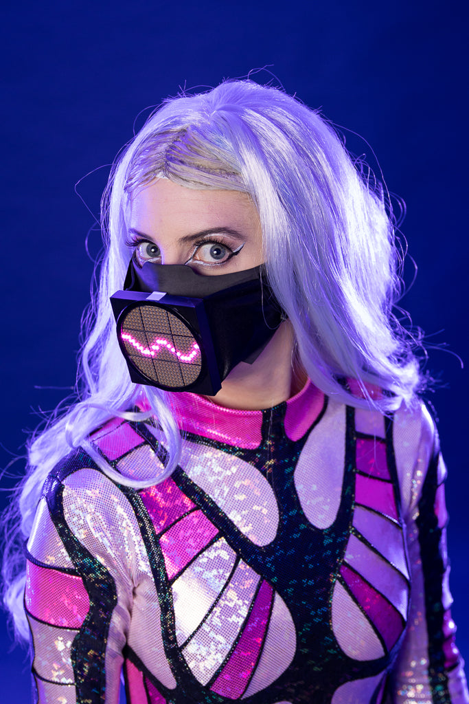
Here's how I made Lady Gaga's sound-reactive LED Matrix Mask for my Lady Gaga Cosplay. In this build, I uncover the actual materials used in Gaga's mask and tweak the design to be a simpler version that’s more appropriate for cosplay.

Code
This sketch displays a similar sine wave to the mask animation, but on the screen.
int xspacing = 24;  // numColumns // How far apart should each horizontal location be spaced
int w;             // waveWidth  // Width of entire wave


float theta = 0.0;  // Velocity // Start angle at 0
float amplitude = 100.0;  // amplitude // Height of wave
//float period = 500.0;  // How many pixels before the wave repeats
float period = 200.0;  // Wavelength // How many pixels before the wave repeats
float dx;  // xIncrement // Value for incrementing X, a function of period and xspacing
float[] yvalues;  // yValues // Using an array to store height values for the wave


void setup() {
  size(480, 480);
  w = width+ xspacing; // width of entire wave
  dx = (TWO_PI / period) * xspacing;
  yvalues = new float[w/xspacing];
}


void draw() {
  background(0);
  calcWave();
  renderWave();
}


void calcWave() {
  // Increment theta (try different values for 'angular velocity' here
  theta = theta + 0.08;


  // For every x value, calculate a y value with sine function
  float x = theta;
  for (int i = 0; i < yvalues.length; i++) {
    yvalues[i] = sin(x)*amplitude;
    x+=dx;
  }
}


void renderWave() {
  noStroke();
  fill(255, 0 , 255);
  // A simple way to draw the wave with an ellipse at each location
  for (int j = 0; j < yvalues.length; j++) {
    ellipse(j*xspacing, height/2+yvalues[j], 16, 16);
  }
}Pink Sine Wave on 24 x 24 DotStar LED Matrix with input from microphone
/*
  This code creates a sin wave on a 24 x 24 DotStar LED Matrix consisting of 9, 8 x 8 Matrices
  Includes input from microphone to control the wave.
*/


#include <Adafruit_GFX.h>
#include <Adafruit_DotStarMatrix.h>
#include <Adafruit_DotStar.h>


#define DATAPIN  12
#define CLOCKPIN 13


#define ONBOARDDATAPIN 8
#define ONBOARDCLOCKPIN 6


#define BRIGHTNESS 16


// Define matrix width and height.
#define mw 24
#define mh 24


#define TWO_PI 6.283185307179586476925286766559


Adafruit_DotStar onboardDotStar(1, ONBOARDDATAPIN, ONBOARDCLOCKPIN, DOTSTAR_BRG);
Adafruit_DotStarMatrix matrix = Adafruit_DotStarMatrix(
                                  (uint8_t)8, (uint8_t)8, 3, 3, DATAPIN, CLOCKPIN,
                                  DS_TILE_TOP   + DS_TILE_LEFT   + DS_TILE_ROWS   + DS_TILE_PROGRESSIVE +
                                  DS_MATRIX_TOP + DS_MATRIX_LEFT + DS_MATRIX_COLUMNS + DS_MATRIX_PROGRESSIVE,
                                  DOTSTAR_BGR);


uint32_t magenta = matrix.Color(255, 0, 255);


// MICROPHONE INPUT (Code based on "Callibration" Analog example in Arduino)
const int micPin = A0;    // pin that the mic is attached to


// variables:
int micValue = 0;         // the mic value
int micMin = 1023;        // min
int micMax = 0;           // max


//WAVELENGTH ATTRIBUTES


int widthOfWholeWave = 24; // Width of the entire wave, I'm using a 24 x 24 matrix.
int wavelength = 12; // How much distance between wave peaks
float velocity = 0.0; // How much does the wave increment / How fast it moves
int amplitude = 8; // How tall is the wave? (Above and below the center)
int xIncrement; // Needed to increment the x values
int yValues[24]; // Stores height values for the wave, I'm using a 24 x 24 matrix.


//int newAmplitude = 10; // New Amplitude after sensor Value


void setup() {


  // Serial
  Serial.begin(9600);


  // Onboard DotStar Setup Stuff
  onboardDotStar.begin(); // initialize the onboard DotStar LED
  onboardDotStar.Color(255, 0, 0); // turn the LED RED to enter recording mode
  onboardDotStar.show();


  // Mic Callibration during the first five seconds
  while (millis() < 5000) {
    micValue = analogRead(micPin);


    // record the maximum sensor value
    if (micValue > micMax) {
      micMax = micValue;
    }


    // record the minimum sensor value
    if (micValue < micMin) {
      micMin = micValue;
    }
  }
  onboardDotStar.Color(0, 0, 0); // turn the LED RED to enter recording mode
  onboardDotStar.show();


  // Matrix Setup
  matrix.begin(); // initialize the matrix
//  matrix.setBrightness(BRIGHTNESS); // set the brightness
  matrix.clear(); // clear the matrix just in case


  // Sine Wave Setup Stuff
  xIncrement = (TWO_PI / wavelength) * widthOfWholeWave;


}


void loop() {


  matrix.clear();
  getMicLevels();
//  calculateWave(2400, amplitude);//*.95
//  drawWave(matrix.Color(random(10,30), random(10,30), random(10,30)), 8);
  calculateWave(9600, amplitude);
  drawWave(magenta, 16);
  matrix.show();
  delay(1);


}


void getMicLevels() {


  amplitude = analogRead(micPin);


  // apply the calibration to the sensor reading
  amplitude = map(amplitude, micMax, micMin, 0, 9);
//    amplitude = map(amplitude, micMin, micMax, 1, 8);


  // in case the sensor value is outside the range seen during calibration
//  amplitude = constrain(amplitude, 0, 12);
}


void calculateWave(int velocityPower, int newAmplitude) {


  velocity = velocity + velocityPower;
  float x = velocity;


  for (int i = 0; i < mh; i++) {
    yValues[i] = sin(x) * amplitude;
    x += xIncrement;
  }
}


void drawWave(uint32_t waveColor, int waveBrightness) {


  matrix.setBrightness(waveBrightness); // set the brightness
  for (int i = 0; i < mh; i++) {
    matrix.drawPixel(i, mh / 2 + yValues[i], waveColor);
  }


}


Natasha from TechnoChic
on June 29, 2024 16:15
Hi coders – if you want to connect join the TechnoChic Discord: https://discord.gg/Yqk7dZnQ5a The Arduino is the software used to create the code for the Itsy Bitsy. And, I remember tweaking the wave code as I was finishing, so it may require some little adjustments every time this project gets built, especially with the calibration. :)
Nick
on June 29, 2024 16:08
Is this the code that you actually ended up using? I’ve built this exactly as shown and the modulation of the sine wave just doesn’t work right.
Thanks for posting it, though!
nick valdez
on September 20, 2021 15:21
first off great job. second…okay so im new to coding. I see that in the pic with the matrix and the its bitsy connected to your laptop that the red black yellow and green wires and connected to the blue grey white and black wires. where are those connected behind the matrix? I noticed that after its coded the blue black grey and white wires are gone and the itty bitsy is soldered to the matrix with the much shorter red black yellow and green wires. I have all the supplies to make this mask I just am not clear on how you coded it. also do I need to use an arudino if you’re using an itsy bitsy? please let me know haha.